

ADDCOMPOSITES BLOG
Load-Dependent Path Planning: Revolutionizing 3D Printing of Continuous Fiber Composites
Introduction
In the rapidly evolving world of advanced manufacturing, continuous fiber reinforced plastics (CFRPs) have emerged as game-changing materials, offering exceptional strength-to-weight ratios and design flexibility. However, the journey from design to final product isn't without its challenges, particularly when it comes to 3D printing these sophisticated materials.
The Challenge of Precision
The core challenge in CFRP 3D printing lies in the precise placement of continuous fibers. While traditional manufacturing methods have served us well, they often fall short when dealing with complex geometries and varying load requirements. The automated fiber placement (AFP) process, though advanced, has historically been limited to simple geometries and restricted areas due to the lack of effective path planning methods.
Why Path Planning Matters
Think of path planning as choreographing a complex dance between the printer and the materials. The direction in which we lay down these continuous fibers isn't just a manufacturing detail – it's a crucial factor that determines the final product's mechanical properties. The relationship between fiber orientation and mechanical strength is particularly critical in high-performance applications.
Current manufacturing methods face several key limitations:
- Difficulty in handling complex geometries
- Limited ability to optimize for varying load conditions
- Risk of fiber breakage in sharp turns
- Challenges in maintaining consistent mechanical properties
A New Approach
Enter Load-dependent Path Planning (LPP) – a revolutionary method that's changing how we approach CFRP 3D printing. This innovative technique doesn't just lay down material; it strategically places fibers based on how the part will be loaded during use. By combining advanced topology optimization with smart path planning, LPP addresses many of the limitations that have historically held back CFRP 3D printing technology.
The engineering behind this process involves sophisticated algorithms and precise control systems, but the core concept is straightforward: align the reinforcing fibers along the natural load paths within a structure. This approach ensures that each fiber contributes optimally to the part's mechanical performance.
In the following sections, we'll dive deep into how this technology works, its advantages over traditional methods, and what it means for the future of composite manufacturing. Whether you're a manufacturing engineer, a design specialist, or simply interested in advanced materials, understanding LPP is crucial for grasping the future of composite manufacturing.
Understanding the Three Main Methods of CFRP 3D Printing
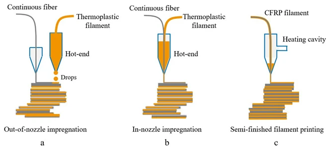
The evolution of composite manufacturing has led to three distinct approaches for 3D printing continuous fiber reinforced plastics. Each method offers unique advantages and faces specific challenges in the quest for optimal fiber placement and material properties.
1. Out-of-Nozzle Impregnation
This method represents one of the fundamental approaches to CFRP 3D printing. Here's how it works:
- Two separate feeders operate simultaneously
- One feeds thermoplastic filament while the other feeds continuous fiber
- The fusion between fiber and plastic occurs outside the nozzle
- The materials combine on the printing bed itself
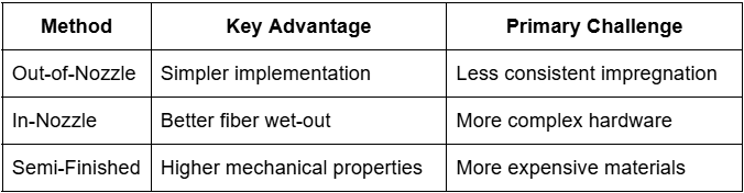
The primary advantage of this approach is its simplicity, but achieving consistent fiber-matrix bonding can be challenging due to the external mixing process.
2. In-Nozzle Impregnation
A more integrated approach to fiber placement, in-nozzle impregnation offers:
- Combined feeding of continuous fiber and thermoplastic filament
- Internal mixing within a specialized hot-end
- Better control over the impregnation process
- More consistent material properties
This method provides better fiber wet-out but requires more complex nozzle designs and careful temperature control.
3. Semi-Finished CFRP Filament Printing
The most advanced of the three methods, this approach uses:
- Pre-fabricated CFRP filament as the printing material
- A specialized heating cavity (either conventional hot-end or microwave resonant cavity)
- Optimized process parameters for enhanced performance
Research has shown that this method achieves superior compressive properties compared to the other two approaches, making it particularly attractive for structural applications.
Comparing the Methods
Each method presents distinct trade-offs:
The Path Forward
While these methods have advanced CFRP 3D printing significantly, they all face a common challenge: the need for effective path planning. Traditional manufacturing approaches often rely on simple patterns like:
- Raster paths
- Zigzag patterns
- Concentric fills
- Contour-parallel paths
However, these conventional approaches don't fully capitalize on the directional strength properties of continuous fibers. This limitation has driven the development of more sophisticated path planning methods, particularly the Load-dependent Path Planning (LPP) approach we'll explore in the next section.
The key to advancing CFRP 3D printing lies not just in perfecting these manufacturing methods, but in developing smarter ways to utilize them. This is where the integration of topology optimization and stress-based path planning becomes crucial for achieving optimal part performance.
The Load-Dependent Path Planning (LPP) Method: A Revolutionary Approach
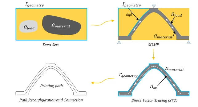
The traditional approach to composite manufacturing has long been constrained by simplified printing patterns that don't fully account for how parts are actually loaded during use. The Load-Dependent Path Planning (LPP) method represents a paradigm shift in how we approach CFRP 3D printing.
The Core Innovation
At its heart, LPP combines three crucial elements:
- Topology optimization
- Stress Vector Tracing (SVT)
- Adaptive printing parameters
This integrated approach to fiber placement creates paths that precisely follow load transmission through the part, resulting in superior mechanical properties.
How LPP Works
Step 1: Topology Optimization
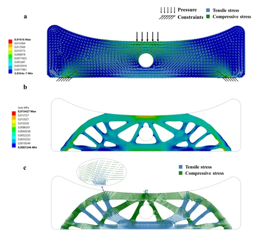
The process begins with a sophisticated optimization method called Solid Orthotropic Material with Penalization (SOMP). This approach:
- Analyzes the original stress distribution
- Reorganizes and simplifies load paths
- Creates an optimized structure focusing on primary load-bearing areas
- Separates tensile and compressive stress regions
Step 2: Stress Vector Tracing (SVT)
The innovative SVT algorithm then:
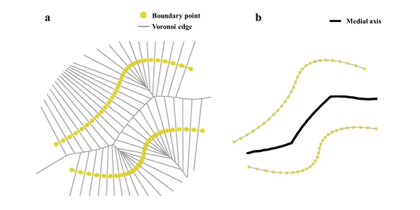
- Extracts the medial axis of the structure using Voronoi diagrams
- Generates continuous printing paths that follow stress vectors
- Optimizes path spacing based on local stress conditions
- Ensures optimal fiber orientation for load bearing
Step 3: Adaptive Speed Control
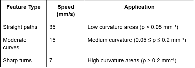
The method incorporates variable printing speeds based on geometric features:
Key Technical Innovations
Geometric Adaptability
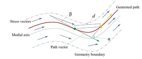
The LPP method considers three critical parameters:
- β: Angle between path segment and stress vector
- α: Angle between adjacent path segments
- d: Distance between nearby points
These parameters are continuously optimized to ensure:
- Smooth fiber placement
- Minimal sharp turns
- Consistent material distribution
- Optimal structural performance
Path Generation Algorithm
The SVT algorithm employs sophisticated mathematics to:
- Calculate path smoothness coefficients
- Optimize path spacing
- Ensure continuous fiber placement
- Avoid fiber breakage in complex geometries
Practical Implementation
The implementation of LPP requires careful consideration of:
- Material Properties
- Young's modulus: E₁ = 18.3 GPa; E₂ = 19.8 GPa
- Poisson's ratio: ν₁₂ = ν₂₁ = 0.17
- Shear modulus: G₁₂ = 5.15 GPa
- Manufacturing Constraints
- Minimum turning radius
- Path continuity requirements
- Process parameter optimization
The Result
This sophisticated approach yields:
- Continuous, uninterrupted printing paths
- Optimal fiber orientation along load paths
- Variable path spacing matching local stress conditions
- Improved mechanical properties in the final part
The LPP method doesn't just create printing paths; it creates an optimized structure that maximizes the inherent strengths of continuous fiber reinforcement while minimizing common manufacturing defects.
Benefits of LPP Over Traditional Methods: A Quantitative Analysis
The traditional approaches to composite manufacturing have served the industry well, but Load-dependent Path Planning (LPP) offers significant advantages that address long-standing challenges in CFRP 3D printing. Let's examine these benefits through quantitative analysis and practical examples.
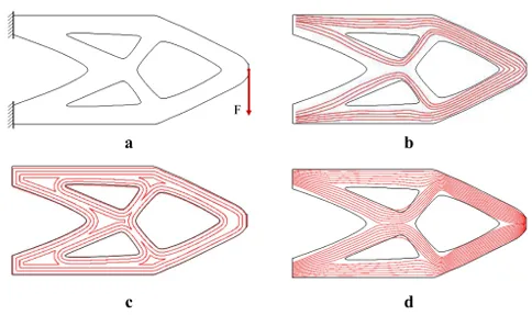
Superior Path Characteristics
Curvature Control
One of the most significant advantages of LPP is its ability to minimize sharp turns and optimize path curvature:
- About 80% of LPP paths maintain curvature below 0.26 mm⁻¹
- Traditional methods frequently reach maximum curvature (4 mm⁻¹)
- Reduced sharp turns mean fewer fiber breakage points
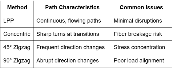
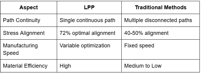
Path Continuity
LPP demonstrates superior path continuity compared to traditional methods:
Stress Distribution Alignment
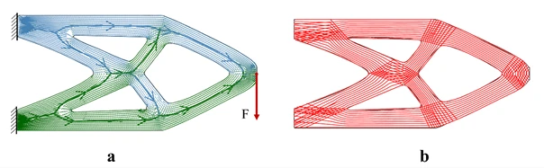
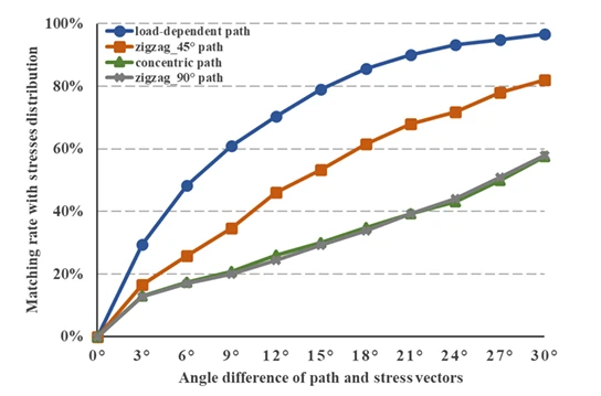
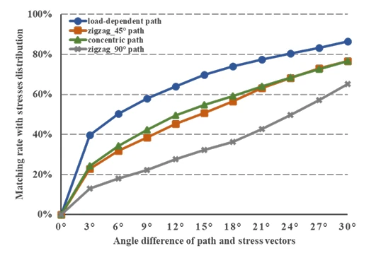
The alignment between fiber orientation and stress distribution is crucial for structural performance. LPP shows remarkable improvements:
- Up to 96.6% of fiber paths align within 30° of principal stress directions
- Traditional methods achieve only 60-80% alignment at best
- Significantly better load transmission characteristics
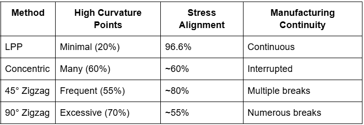
Matching Rate Comparison
When analyzing the bridge part example:
- LPP: 96.6% stress vector alignment
- 45° Zigzag: ~80% alignment
- Concentric: ~60% alignment
- 90° Zigzag: ~55% alignment
Manufacturing Efficiency
Speed Optimization
LPP's adaptive speed control provides:
- 35 mm/s in straight sections
- 15 mm/s in moderate curves
- 7 mm/s in sharp turns
This variable speed approach results in:
- Reduced manufacturing time
- Better fiber placement accuracy
- Improved part quality
- Fewer manufacturing defects
Geometric Versatility
Complex Shape Handling
LPP excels in managing challenging geometries:
- Bridge Parts
- Seamless integration of varying stress patterns
- Continuous paths across complex transitions
- Optimal fiber placement in critical areas
- Suspension Components
- 72% of paths maintain low curvature
- Effective handling of holes and transitions
- Balanced stress distribution
Joint Areas
Unlike traditional methods, LPP specifically addresses joint areas through:
- Cross-path reinforcement
- Variable path density
- Optimized fiber orientation in high-stress regions
Material Efficiency
LPP optimization leads to:
- Reduced material waste
- Better fiber utilization
- Optimized part strength-to-weight ratio
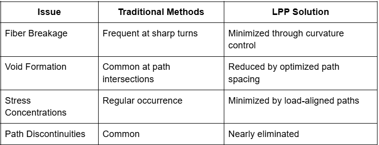
Common Manufacturing Issues Addressed
Future Implications
The benefits of LPP extend beyond current applications:
- Enabling more complex geometries
- Supporting higher performance requirements
- Advancing sustainable manufacturing practices
- Reducing material waste and production costs
These quantifiable improvements demonstrate why LPP represents not just an incremental improvement, but a fundamental advancement in CFRP manufacturing technology.
Technical Implementation: Making Load-Dependent Path Planning Work
The practical implementation of advanced manufacturing techniques requires careful attention to detail. Let's dive into how Load-Dependent Path Planning (LPP) transforms from theory to practice.
The Implementation Pipeline
1. Initial Data Processing
The process begins with three key data sets:
- Ωmaterial (Material Set)
- Ωload (Load Set)
- Γgeometry (Geometry Boundary)
These foundational elements form the basis for all subsequent calculations.
2. Topology Optimization Process
The system uses the SOMP (Solid Orthotropic Material with Penalization) method, expressed mathematically as:
min: c(ρ,θ) = U^T KU = ∑[T_min + (ρ_e)^P (T_0 - T_min )]u_e^T k_θu_e
Where:
- ρ represents density
- θ represents fiber orientation
- U represents displacement vector
- K represents stiffness matrix
This optimization considers:
- Volume constraints
- Material properties
- Load conditions
- Structural requirements
3. Stress Vector Tracing (SVT) Algorithm
Step 1: Medial Axis Extraction
- Uses Voronoi diagram approach
- Processes boundary points
- Generates equidistant lines
- Creates geometric backbone
Step 2: Vector Tracing
The algorithm evaluates three critical parameters:
α = cos^(-1)((v_pl · v_pn)/(|v_pl||v_pn|)) // Path segment angle
β = cos^(-1)((v_pn · v_stress)/(|v_pn||v_stress|)) // Stress alignment
d = distance between points // Path spacing
4. Path Generation Controls
The path generation process incorporates several control mechanisms:
# Evaluation criterion for path smoothness
γ(z)_z=α,β,d = -((z/z_limit)^(k_z·η-ε)/k_z) + ε
# Overall smoothness coefficient
δ = ∏γ(z) where z∈{α,β,d}
Speed Control Implementation
The system implements variable speed control based on geometric features:
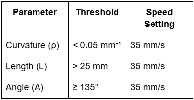
Adaptive Speed Transitions
- Smooth acceleration/deceleration profiles
- Path-dependent speed adjustments
- Real-time curvature monitoring
Quality Control Measures
1. Path Validation
- Continuous connectivity checking
- Curvature limit enforcement
- Stress alignment verification
2. Manufacturing Constraints
The implementation considers:
- Minimum turning radius
- Maximum acceleration
- Tool path accessibility
- Material-specific limitations
Error Handling and Optimization
Error Prevention
- Geometric Validation
- Boundary checking
- Path intersection detection
- Spacing verification
- Process Parameters
- Temperature control
- Feed rate adjustment
- Tension monitoring
Optimization Loops
The system continuously optimizes for:
1. Path smoothness
2. Stress alignment
3. Manufacturing efficiency
4. Material usage
Implementation Workflow
- Pre-processing
- Load analysis
- Boundary definition
- Material parameter setting
- Processing
- Topology optimization
- Path generation
- Speed profile creation
- Post-processing
- Path validation
- Manufacturing instruction generation
- Quality control parameter setting
This technical implementation ensures that LPP delivers not just theoretical benefits but practical, manufacturable results that can be consistently reproduced in real-world applications.
Case Studies: LPP in Action
The true test of any manufacturing innovation lies in its practical application. Let's examine how Load-dependent Path Planning (LPP) performs in real-world scenarios through two detailed case studies.
Case Study 1: Three-Point Bending Bridge
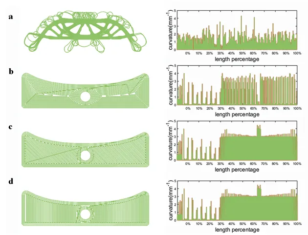
Component Specifications
- Width: 185 mm
- Height: 50 mm
- Design Requirements:
- High load-bearing capacity
- Minimal material usage
- Continuous fiber reinforcement
Analysis Process
- Initial Load Analysis
- External force application at center
- Two support conditions at ends
- Complete stress distribution mapping
- Optimization Results
- Stress vectors reorganized into clear patterns
- Distinct separation of tensile and compressive zones
- Medial axis alignment with load paths
Manufacturing Implementation
The LPP method generated paths with:
- Variable spacing (stress-dependent)
- Three-speed profiles:
- 35 mm/s for straight sections
- 15 mm/s for moderate curves
- 7 mm/s for complex transitions
Performance Metrics
- 80% of curves maintained curvature below 0.26 mm⁻¹
- 96.6% stress vector alignment within 30°
- Continuous fiber placement throughout
- Zero sharp turns in critical areas
Case Study 2: Suspension Part
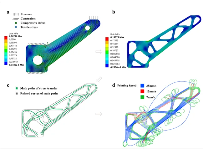
Component Characteristics
- Width: 175 mm
- Height: 126 mm
- Complex loading conditions:
- Compressive load on cantilever
- Fixed bottom supports
- Multiple stress concentration zones
Optimization Process
- Topology Analysis
Initial State → Optimization → Final Design
- Material distribution optimized
- Load paths identified
- Critical zones mapped
Manufacturing Outcomes
The suspension part demonstrated:
- 72% of paths with curvature below 0.26 mm⁻¹
- 20% higher stress vector matching compared to traditional methods
- Smooth transitions in complex geometries
- Efficient material usage
Comparative Analysis with Traditional Methods
Bridge Part Comparison
Suspension Part Performance
Key Learnings
- Geometric Adaptability
- LPP successfully handled complex transitions
- Maintained fiber continuity in challenging areas
- Adapted to varying cross-sections
- Manufacturing Efficiency
- Reduced waste through optimized paths
- Minimized tool path transitions
- Improved production speed through adaptive control
- Quality Improvements
- Better fiber orientation control
- Reduced likelihood of defects
- More consistent part properties
- Process Reliability
- Reproducible results
- Consistent quality metrics
- Stable manufacturing parameters
These case studies demonstrate that LPP isn't just theoretically superior – it delivers measurable improvements in real-world manufacturing scenarios. The method's ability to handle complex geometries while maintaining optimal fiber placement makes it a significant advancement in CFRP manufacturing technology.
Future Implications and Conclusions: The Road Ahead for Composite Manufacturing
The shift in composite manufacturing from traditional methods to advanced, algorithm-driven approaches represents more than just technological progress – it's a fundamental reimagining of how we design and produce composite parts. Let's explore what the development of Load-dependent Path Planning (LPP) means for the future of the industry.
Transformative Impact
Immediate Benefits
- Manufacturing Efficiency
- Reduced material waste
- Optimized production speeds
- Improved quality control
- Better resource utilization
- Design Capabilities
- Complex geometry handling
- Load-optimized structures
- Improved part performance
- Weight optimization
- Quality Improvements
- Consistent fiber placement
- Reduced defect rates
- Better structural integrity
- Enhanced reliability
Industry Applications
Aerospace
- Complex aerostructures
- Light-weight components
- High-performance parts
- Safety-critical applications
Automotive
- Structural components
- Lightweight chassis elements
- Performance optimization
- Electric vehicle components
Energy Sector
- Wind turbine blades
- Pressure vessels
- Structural supports
- Energy storage systems
Future Development Paths
1. Algorithm Enhancement
- Machine learning integration
- Real-time optimization
- Adaptive process control
- Enhanced path prediction
2. Material Innovation
Current Focus Areas:
- Advanced fiber types
- Matrix material development
- Hybrid material systems
- Sustainable materials
3. Process Integration
- Digital twin implementation
- IoT sensor networks
- Quality monitoring systems
- Automated adjustment systems
Challenges to Address
- Technical Challenges
- Computing power requirements
- Real-time processing needs
- Complex geometry handling
- Material behavior prediction
- Implementation Challenges
- Training requirements
- Infrastructure needs
- Cost considerations
- Industry adoption barriers
Research Directions
Near-Term Focus
- Process Optimization
- Speed improvements
- Quality enhancement
- Defect reduction
- Cost reduction
- Material Development
- New fiber types
- Matrix improvements
- Hybrid systems
- Recycling solutions
Long-Term Goals
- Autonomous Manufacturing
- Self-optimizing systems
- Predictive maintenance
- AI-driven process control
- Full automation
- Sustainability Integration
- Eco-friendly materials
- Energy efficiency
- Waste reduction
- Circular economy adoption
Conclusion
The development of Load-dependent Path Planning represents a significant milestone in composite manufacturing. Its success demonstrates that:
- Intelligent Manufacturing is Achievable
- Algorithm-driven processes work
- Real-world implementation is viable
- Benefits are quantifiable
- Integration is practical
- Future Growth is Promising
- Technology continues to evolve
- Applications are expanding
- Industry adoption is growing
- Innovation is accelerating
- Industry Impact is Substantial
- Manufacturing efficiency improves
- Part quality increases
- Design capabilities expand
- Sustainability advances
The path forward is clear: the future of composite manufacturing lies in intelligent, adaptive systems that optimize every aspect of the production process. LPP is not just a new manufacturing method – it's a stepping stone toward the next generation of composite manufacturing technology.
References
Primary Research
This blog post is based on the research paper:
Wang, T., Li, N., Link, G., Jelonnek, J., Fleischer, J., Dittus, J., & Kupzik, D. (2020). "Load-dependent Path Planning Method for 3D Printing of Continuous Fiber Reinforced Plastics." Karlsruhe Institute of Technology, Germany.
Related Resources from Addcomposites
Technical Guides
- Introduction to Composite Materials
- What is Automated Fiber Placement (AFP)?
- Understanding Composites in Production Machines
Advanced Manufacturing
- Revolutionizing 3D Printed Composites
- Process Monitoring AI for AFP Composites Manufacturing
- Path Planning and Simulation Platform
Industry Applications
Take the Next Step in Composite Manufacturing
Are you ready to revolutionize your composite manufacturing process? Addcomposites offers cutting-edge solutions that bring the power of advanced path planning and automated fiber placement to your facility.
Why Choose Addcomposites?
- State-of-the-art AFP technology
- Expert technical support
- Comprehensive training programs
- Flexible implementation options
- Industry-leading innovation
Get Started Today
- Schedule a Consultation Contact our team of experts to discuss your specific manufacturing needs.
- Request a Demo See our technology in action and understand how it can transform your production process.
- Join Our Community Stay updated with the latest developments in composite manufacturing.
This blog post is part of Addcomposites' commitment to advancing composite manufacturing technology. The technical content is based on research conducted at the Karlsruhe Institute of Technology, with permission from the authors. For more information about our products and services, visit www.addcomposites.com.
About the Research
The original research was conducted at the Karlsruhe Institute of Technology, focusing on developing more efficient and effective methods for 3D printing continuous fiber reinforced plastics. We thank the authors for their groundbreaking work in advancing composite manufacturing technology.