

ADDCOMPOSITES BLOG
Cutting Car Door Weight by 15% With Layups You Can Actually Manufacture
A 2024 Applied Sciences study built manufacturing constraints into a CFRP car door optimizer; its plain-weave design cut mass 15.85% to 13.43 kg from a 15.96 kg metal baseline while meeting stiffness targets.
Most lightweighting studies stop at a laminate that looks great on paper and skip whether a real process could ever lay it down. A study published in January 2024 in Applied Sciences (MDPI) does the opposite, and it makes the same criticism of earlier work, noting that prior door designs "seldom consider the process constraints related to CFRP layup angles" (p. 2). Working with an actual car door under development at a real automotive manufacturer, the authors encode composite layup process constraints directly into the optimizer, so every candidate design it evaluates already obeys real manufacturing rules. Our read: that is what separates a buildable result from a theoretical stack that ignores ply-drop and stacking-sequence limits.
The paper, by Huile Zhang, Zeyu Sun, Pengpeng Zhi, Wei Wang, and Zhonglai Wang, is titled "Material-Structure Integrated Design and Optimization of a Carbon-Fiber-Reinforced Composite Car Door." Everything below labeled as coming from the paper is the authors' work; anything fenced as an Addcomposites observation or our perspective is our own commentary and does not represent a position of the authors.
The single heaviest target: the inner panel
The paper starts by weighing the problem, literally. According to the authors, the baseline metal door assembly comes to 15.96 kg, and the inner panel alone accounts for 6.12 kg of that. That is 38.34 percent of the door sitting in one component.
Baseline metal door · mass breakdown
Where the 15.96 kg of a metal door actually sits
A single inner panel carries 38.3% of the door's mass; the remaining 61.7% is spread across everything else.
Inner-panel figures: Zhang et al., Appl. Sci. 2024, 14, 930 (Sec. 3.1). Remainder (9.84 kg / 61.7%) is our arithmetic.
When more than a third of an assembly's weight is concentrated in a single part, that part is where a weight-reduction program earns its keep. The paper makes the inner panel the focus of its equal-stiffness replacement, and that framing is what makes the rest of the work concrete rather than academic.
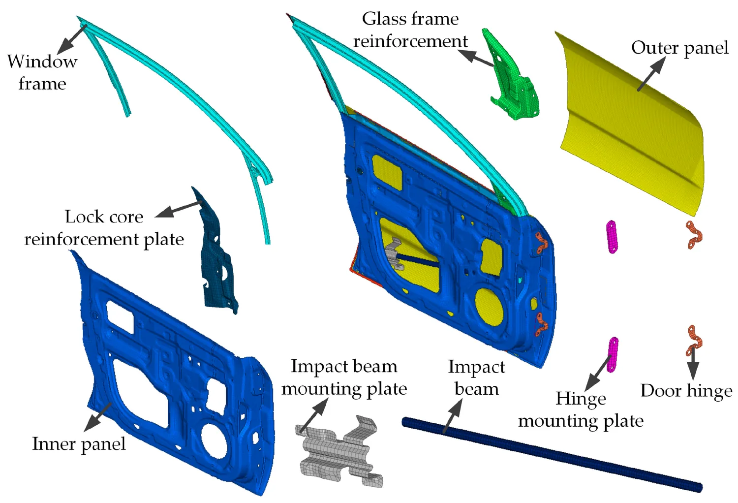
Figure 9 from: Huile Zhang, Zeyu Sun, Pengpeng Zhi, Wei Wang, Zhonglai Wang. "Material-Structure Integrated Design and Optimization of a Carbon-Fiber-Reinforced Composite Car Door." Applied Sciences 2024, 14, 930. https://doi.org/10.3390/app14020930 — © 2024 by the authors. Licensed under CC BY 4.0 (https://creativecommons.org/licenses/by/4.0/).
Three scales, one part
At the microscale, the material is fiber and resin, and the property that dominates is the fiber volume fraction. At the mesoscale, those homogenized fibers become yarns woven into a fabric, and the pattern of that weave, plain, twill, or satin, changes the behavior. At the macroscale, single plies are stacked into the laminate that becomes the door. The authors implement the property transfer across these scales through Python scripting, and they predict the elastic behavior at each level using a homogenization approach driven by thermal stress in ABAQUS.
A mechanical shortcut worth noting: the authors apply thermal loads and read the resulting strains to extract the stiffness of a representative volume element, running six thermal-stress scenarios in all, one per stiffness component (paper Fig. 3). The paper reports that this thermal-stress route reproduced experimental values from prior literature closely.
Validation / microscale cell
Predicted vs. measured elastic properties of a unidirectional carbon/epoxy cell
Four properties, one microscale cell: the thermal-stress model lands within 3.03 % of published experiment on every one of them, with the Poisson's ratio mu12 the widest gap.
Error bars are scaled to the largest gap in the set (3.03 %). mu12 is highlighted: 0.34 predicted against 0.33 measured.
Values reported in Zhang et al., Appl. Sci. 2024, 14, 930 (Table 2)
The authors note that Poisson's ratio drifted the most, by roughly 3 percent, and they judge the method reliable given normal experimental scatter.
(Materials, for reference: the study uses T700-12k carbon fiber with EPOLAM 5015 epoxy resin, at a fiber volume fraction of 51 percent for the unidirectional yarn inputs.)
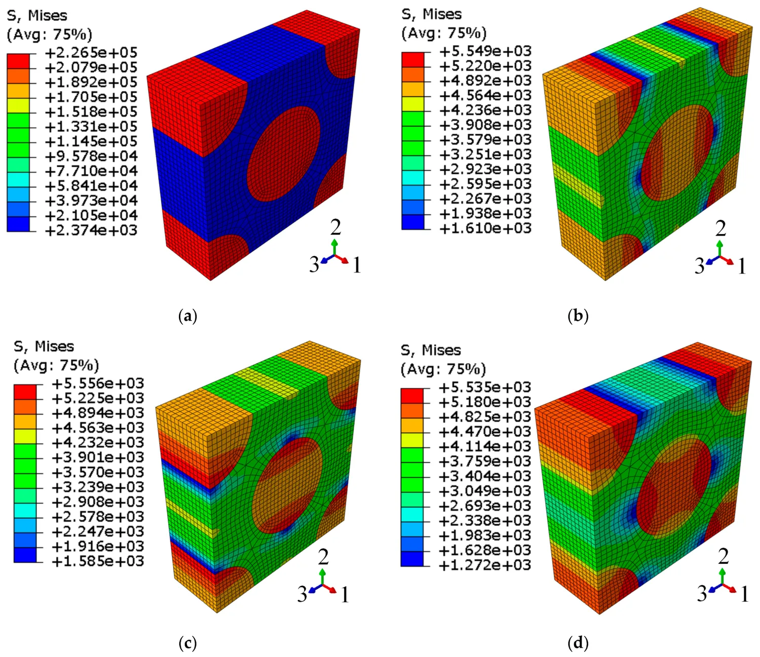
Figure 3 from: Huile Zhang, Zeyu Sun, Pengpeng Zhi, Wei Wang, Zhonglai Wang. "Material-Structure Integrated Design and Optimization of a Carbon-Fiber-Reinforced Composite Car Door." Applied Sciences 2024, 14, 930. https://doi.org/10.3390/app14020930 — © 2024 by the authors. Licensed under CC BY 4.0 (https://creativecommons.org/licenses/by/4.0/).
What the weave actually changes
Once the yarns are woven, the pattern matters. The paper analyzes plain, twill, and satin weaves and reports their single-ply elastic properties. The differences are real but not dramatic, which is itself a useful finding: across plain, twill, and satin, the reported stiffness values stay within a fairly narrow band, so no single weave runs away from the others.
Material data · single-ply woven
In-plane stiffness of three woven architectures
For a balanced weave the in-plane moduli are equal, E1 = E2. Twill is the stiffest of the three; plain sits in the middle and is the weave chosen for this laminate.
In-plane elastic modulus E1 = E2, in GPa
Reported in Zhang et al., Appl. Sci. 2024, 14, 930 (Table 4). Addcomposites-created visualization.
The paper also traces how each volume fraction drives properties. At the microscale, the authors report that as fiber content climbs, axial stiffness (E1) tracks a nearly straight line, whereas the transverse and shear moduli (E2, G12) start slow and steepen; Poisson's ratio moves the opposite way, dropping off. At the yarn level the effect is steadier: more yarn content lifts the moduli in near-proportion rather than curving.
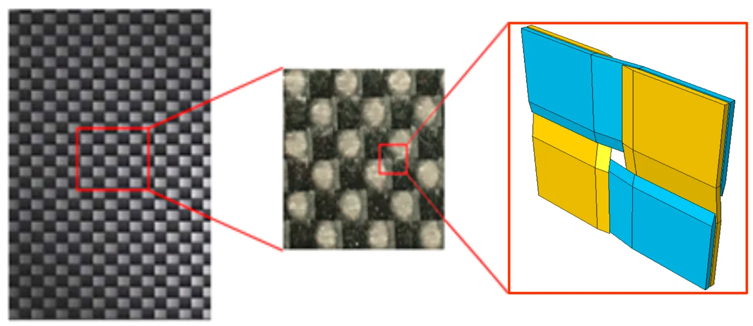
Figure 7 from: Huile Zhang, Zeyu Sun, Pengpeng Zhi, Wei Wang, Zhonglai Wang. "Material-Structure Integrated Design and Optimization of a Carbon-Fiber-Reinforced Composite Car Door." Applied Sciences 2024, 14, 930. https://doi.org/10.3390/app14020930 — © 2024 by the authors. Licensed under CC BY 4.0 (https://creativecommons.org/licenses/by/4.0/).
Defining "good enough" for a door
A door cannot simply be lighter; it has to stay stiff enough to feel solid and safe. The paper anchors its stiffness targets to the SAIC Passenger Car Door Rigidity Test Specification and sets three displacement limits plus a resonance limit. The authors lay out the load cases as follows.
Door stiffness · load cases
Four load cases the closed door must survive
Hinges fixed, lock core constrained. Three displacement limits and one modal limit.
Displacement limits — shared 0–10 mm scale
The free-modal case sets a frequency floor rather than a displacement, so it sits outside the millimetre scale above: f > 35 Hz.
Conditions per Zhang et al., Appl. Sci. 2024, 14, 930 (Table 5, Fig. 10). Addcomposites-created visualization.
The design philosophy is "equal stiffness": replace the metal inner panel with a composite one that behaves at least as well against these limits. The paper reports that a first-pass composite design, using a 35 percent fiber volume fraction, a 0.35 mm ply thickness, and 12 layers, already met every constraint while dropping the door from 15.96 kg to 13.47 kg, and it raised the first natural frequency from 38 Hz to 42 Hz. That preliminary design is the starting line, not the finish.
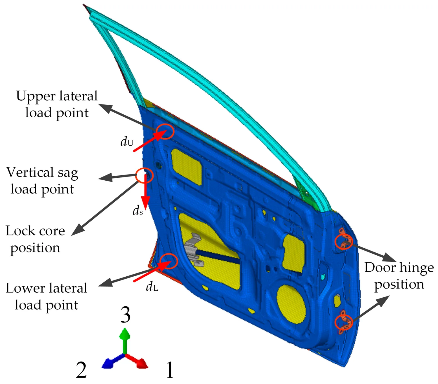
Figure 10 from: Huile Zhang, Zeyu Sun, Pengpeng Zhi, Wei Wang, Zhonglai Wang. "Material-Structure Integrated Design and Optimization of a Carbon-Fiber-Reinforced Composite Car Door." Applied Sciences 2024, 14, 930. https://doi.org/10.3390/app14020930 — © 2024 by the authors. Licensed under CC BY 4.0 (https://creativecommons.org/licenses/by/4.0/).
The part most optimizers skip: manufacturing rules
Here is where the paper separates itself. Plenty of studies will optimize ply angles and hand back a stack that is lighter and stiffer. The problem is that such a stack often cannot be built without warping, delamination, or a layup a real process refuses to place. The authors instead encode four composite layup process constraints directly into the optimizer so that every candidate design the algorithm considers is already manufacturable.
The paper defines the four rules this way:
Layup process constraints
Four constraints the optimizer checks on every ply stack
A candidate layup must clear all four checks before it is scored. Rule 4, the cap on identical consecutive plies, is highlighted.
-
1
Enforced
Allowed angles only
Plies restricted to -45, 0, +45, 90 degrees
-
2
Enforced
Balanced symmetry
Layer u must mirror layer (13 - u)
-
3
Enforced
Plus/minus 45 pairing
Every +45 has a matching -45 to resist warping
-
4
Enforced
No 4-in-a-row same angle
Caps consecutive identical plies to limit delamination
Source: Rules as specified in Zhang et al., Appl. Sci. 2024, 14, 930 (Sec. 4.1). Addcomposites-created visualization.
To make an optimizer respect rules like these, the authors modified a Multi-Objective Particle Swarm Optimization (MOPSO) algorithm, changing how it generates and updates candidate solutions so that infeasible layups are steered out rather than penalized after the fact. The full optimization was set up to minimize two objectives at once, door mass and vertical sag displacement, while holding the torsional limits, the frequency floor, and a Tsai-Wu failure index between 0 and 1 as constraints. The design variables mixed three continuous geometry terms (microscale cell size, yarn width, yarn thickness) with twelve discrete ply-angle choices.
A symmetric, balanced 12-ply stack that obeys those rules looks like this, using the plain-weave optimum the paper reports:
Stacking sequence
A 12-ply balanced-symmetric laminate, mirrored about the midplane
Each bar is one ply in the cured stack. Every ply above the midplane has a mirror partner below it, and the ±45 plies flip sign across the midplane.
Layup [0/45/-45/0/90/0/0/90/0/45/-45/0] reported in Zhang et al., Appl. Sci. 2024, 14, 930 (Sec. 5)
What the trade-off costs, and what it buys
Because mass and sag stiffness pull against each other, there is no single "best" door, only a frontier of compromises. The paper presents Pareto solution sets for all three weaves, both with and without the manufacturing constraints turned on. The authors report a clear pattern: the constrained solutions sit up and to the right of the unconstrained ones, meaning the manufacturable designs give up a little mass and a little stiffness compared to the theoretical-but-unbuildable set.
The authors are explicit about why: the manufacturing rules shrink the feasible design space, so some of the lightest, stiffest points are simply off the table because no valid layup reaches them. They point to a concrete example in which the unconstrained set contained designs with four identical plies stacked in a row, exactly the situation rule 4 exists to prevent.
To pick a single design off each frontier, the paper uses a minimum-distance selection method. The resulting weight reductions against the metal baseline are the headline result:
Optimized door panel · weave comparison
Plain weave removes the most weight from the metal door
Final, constraint-compliant mass reduction against a 15.96 kg metal baseline. Bars are scaled to a 16% ceiling.
Metal baseline: 15.96 kg
Note: the paper's twill figures don't reconcile — 13.48 kg against 15.96 kg is 15.54%, not 14.54%; percentages shown as reported.
Reported in Zhang et al., Appl. Sci. 2024, 14, 930 (Table 7). Note: the paper's twill figures don't reconcile - 13.48 kg against 15.96 kg is 15.54%, not 14.54%; percentages shown as reported. Addcomposites-created visualization.
a 15.96 kg baseline is a 15.54% cut, not 14.54%. Percentages are
shown here as the paper reports them.
The paper reports that all three optimized doors still cleared the sag, torsional, and frequency requirements, with plain weave delivering the best weight reduction at 15.85 percent. In other words, the manufacturable set did not just come close; it met the full performance spec while trimming roughly one part in six from the door's mass.
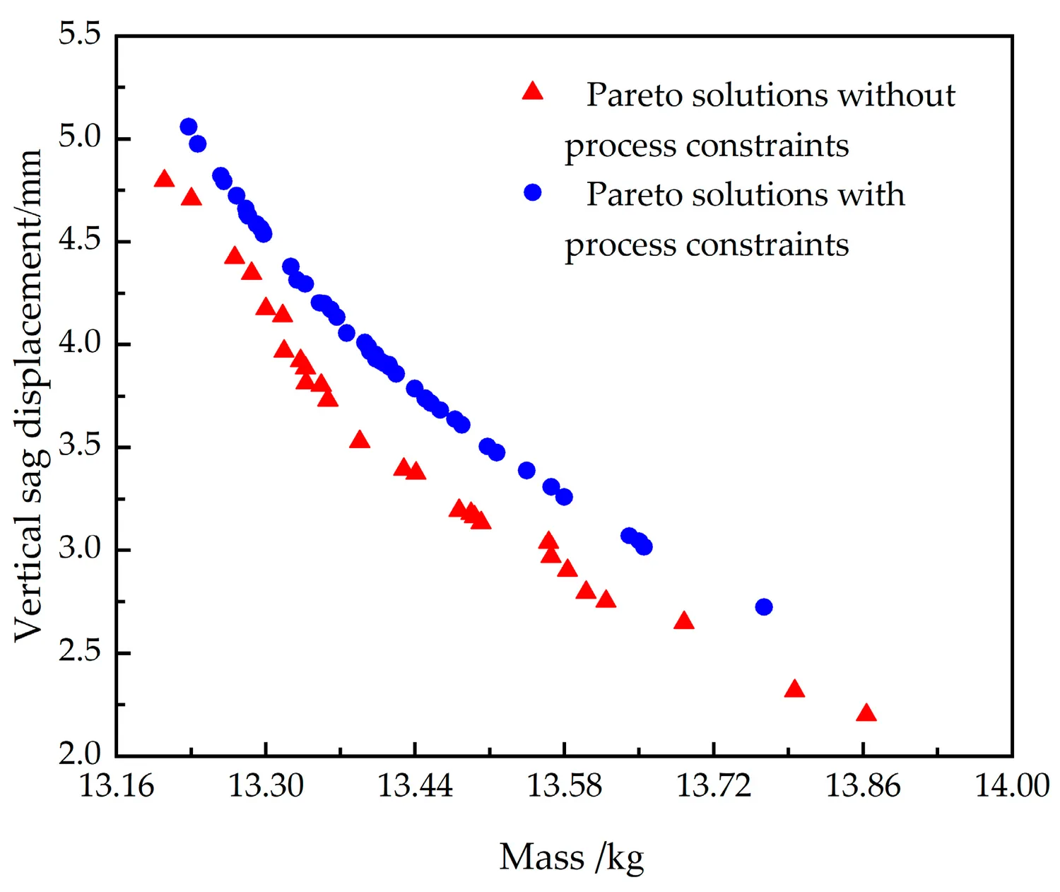
Figure 13 from: Huile Zhang, Zeyu Sun, Pengpeng Zhi, Wei Wang, Zhonglai Wang. "Material-Structure Integrated Design and Optimization of a Carbon-Fiber-Reinforced Composite Car Door." Applied Sciences 2024, 14, 930. https://doi.org/10.3390/app14020930 — © 2024 by the authors. Licensed under CC BY 4.0 (https://creativecommons.org/licenses/by/4.0/).
From a Pareto point to a placed ply
A design like the plain-weave optimum is a specification: a fiber volume fraction, a yarn volume fraction, and an ordered stack of twelve angles that already respects symmetry, pairing, and stacking limits. Turning that specification into a part is a fiber placement problem.
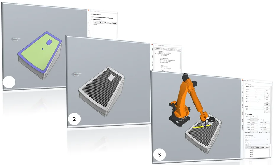
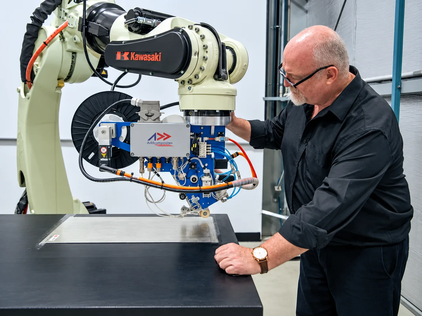
For a door inner-panel program at prototype or low-to-moderate volume, the AFP-XS is our default recommendation. It is a compact, single-tow system that upgrades an existing industrial robot into a fiber placement cell, works across thermoset, thermoplastic, towpreg, and dry-fiber materials, and is aimed squarely at research and small-scale production. For higher-volume door production where throughput drives the line, our four-tow AFP-X adds capacity and sensing for high-volume manufacturing. Which system fits depends on the program's volume and cadence, not on the layup design itself, since the manufacturable stack the paper produces is agnostic to the machine that lays it.
Where this points next
The authors present the workflow as generalizable: shown on the door, but written to carry over to other structural parts of the vehicle.
For AFP manufacturers pitching structural composite programs to OEMs, the value is twofold: a quantified argument for where composite redesign pays off, and a design methodology whose output is manufacturable by construction. The second point is the one that tends to get lost, and it is the one worth carrying into your next program conversation.
Read the Research
Huile Zhang, Zeyu Sun, Pengpeng Zhi, Wei Wang, Zhonglai Wang. "Material-Structure Integrated Design and Optimization of a Carbon-Fiber-Reinforced Composite Car Door." Applied Sciences 2024, 14, 930. https://doi.org/10.3390/app14020930
Open access, published 22 January 2024, under the Creative Commons Attribution (CC BY 4.0) license: https://creativecommons.org/licenses/by/4.0/
The ASCII diagrams in this post are original visualizations created by Addcomposites to represent data and relationships reported in the paper; they are not reproductions of the paper's figures.